I. Diffraction from a single slit
A laser beam is directed unto a narrow slit and a diffraction pattern is observed at a screen placed sufficiently far from the slit. Diffraction is observed in this setup due to the self-interference of the light beam. Recalling Huygen’s principle, every point of a wave front can be considered a light source. Waves from these point sources interfere with each other and form a diffraction pattern with bright and dark bands.
We consider the light wave coming to the slit as plane waves. As the plane wave arrives at the slit, secondary waves spread out in-phase. Assuming that the distance between the slit and the screen L is very large, the rays from every secondary wavelets can be considered to be parallel but converges at point P(x=∞, y). This is why L must be very large compared to the slit width a. The setup in-principle is shown below.
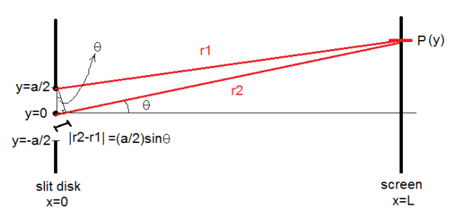
Figure 1. Slit with width a and a screen L (very large) distance away from the slit.
In the interest of locating the intensity minima (destructive interference), let P be a minima. Consider first dividing the slit in half such that given a point in the slit A(x=0, y≥0), there corresponds another point in the slit A'(x=0, y≤0) such that the distance between A and A’ is always a/2. For a particular pair (A ,A’)=(y=a/2, y=0) as shown in Figure 1, the path difference |r2-r1| must be m(λ/2), where m is an odd number, in order for the two waves to arrive at P completely out of phase. Since there exist a one-to-one correspondence (A, A’) that spans every point in the slit, the total sum of every wavelet in the slit is therefore zero at P, that is, if a is very small such that |r2-r1| for any given (A, A’) is conserved. Finally, we see that there is a minima at y if and only if
y = mλL/a
(1)
So far, the allowable values for n are odd integers. However, if the slit is divided into k parts (k=2 in the previous analysis), where k is an even number, there is also a one-to-one correspondence (A, A’) that spans every point in the slit where the the distance between A and A’ is conserved: dist(A, A’)=a/k. This gives to another set of minima. Thus, in (1) m can be any integer since k is always even. Negative integers corresponds to minima below y=0.
Knowing the values of the other variables (which are mostly lenghts), the wavelength of the light used can be determined using the setup.
For calculating the actual L which is strictly the length that light has traveled from the slit to the screen, the following method is applied:
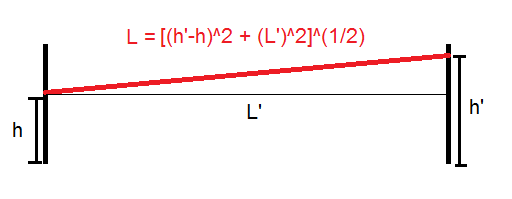
Figure 2. Calculation for actual L. Slit and diffraction pattern is positioned at height h or h’.
The y value for the minima are determined by taking the width of the bright bands and dividing by 2 to get the distance from the center.
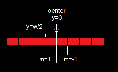
Figure 3. Experimental measurement of y.
Table 1 summarizes the data for this part of the experiment.
Table 1. Data for single slit diffraction.
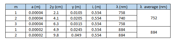
The light source used is a red laser. The wavelength of red light lies at 650-750 nm [1]. For the 0.04 mm slit, the calculated average wavelength falls at the range while the wavelength from 0.02 mm slit is off by 18% from the upper bound of the range. One very significant source of error is deciding where the dark band is actually located at the pattern. The dark parts of the pattern are wider than expected. However, not all of these parts correspond to y. These are not points of completely destructive interference, but light intensity at these parts may only be actually very low. It is considered that the middle of the dark bands corresponds to y. But, locating the middle is often left to the decision of the experimenter and thus subjective. In fact, for m=1, a=0.02 mm every 1 mm measurement of y adds 36 nm to the wavelength calculation.
II. Interference from two slits:
A. Fringes
In this part, the same setup is applied but the configuration of the slit is changed: two slits are used instead of just one. Here, an interference pattern is observed on the screen located a distance L from the slits.
We invoke the same assumptions and approximations from the previous analysis in diffraction. Taking into account the interference alone of the waves from the two slits, we neglect the effects of diffraction. Thus, the slits are considered to be very narrow such that there is only one point in which a wavelet originate. The interference then is between the wavelets from each slit. The setup in-principle is shown in the figure below.
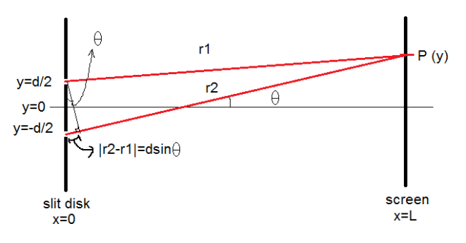
Figure 4. Interference from two slits. One wavelet per slit is considered. The interference pattern is due to the interference of the two point sources.
The pattern seen in the screen is due to the constructive and destructive interference of the waves. For a varying point in the screen P(x=L, y), the distance that the wavelets travel varies as well and the difference of these path lengths causes alternating bright and dark fringes to form. At a point where there is completely no light (minima), the waves arrive completely out of phase, i.e., |r2-r1|=(n+1/2)λ, where n is any integer. Meanwhile, at the brightest part of the bright fringes (maxima), the waves arrive in phase, i.e., |r2-r1|=nλ, where n is an integer. Finally, we see the following relations hold:
y = nλL/d
(2, intensity maxima)
y = (n+1/2)λL/d
(3, intensity minima)
We can also see that the Δy between two successive maxima and minima is λL/2d. Intuitively, the center of the bright fringes are the location of the maxima and the center of the dark fringes correspond to the minima. Then, the width w of the bright fringes is just twice the Δy
w = λL/d
(4)
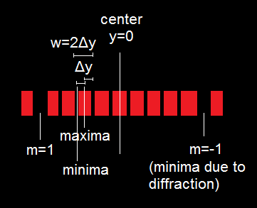
Figure 5. Derivation of (4).
Alternatively, w can be measured approximately by measuring the width of the bright bands (by diffraction envelope) and dividing by the number of its bright fringes.
Table 2. Theoretical and experimental width of bright fringes.
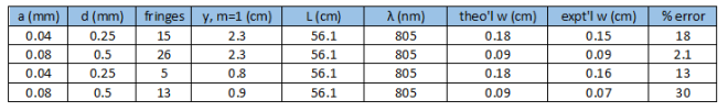
From Table 2, to some extent the theoretical and experimental values for the width are consistent with each other. Errors arise mostly from the sensitivity of the setup (dealing with values in the magnitude of 10^(-3)) and deciding which fringes at the sides of a diffraction envelope belong to a band.
B. Calculating the slit width.
Equation (1) provides an expression for the slit width a. Using the setup for double slit interference and with a known value of the wavelength, a can be calculated.
The slit configuration is a=0.04 mm, d=0.25 mm. The labeled wavelength of the laser source was not noted, unfortunately. The average of the wavelength calculation in the single slit diffraction was used: 804 nm.
Table 3. Slit width calculation.
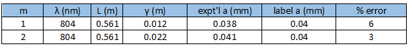
Table 3 shows high accuracy of the theoretically determined a compared to the labeled slit width. The equation used for the calculation of a is (1) which applies to a single slit. The high accuracy of data implies that the diffraction envelope pattern of the double slit setup still depends on the slit width a.
III. Appendix

Figure 6. General setup showing a single slit diffraction pattern.
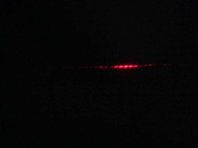
Figure 7. Interference pattern of slit configuration: a=0.08 mm, d=0.25 mm. The first bright band of the diffraction envelope is divided by five fringes.
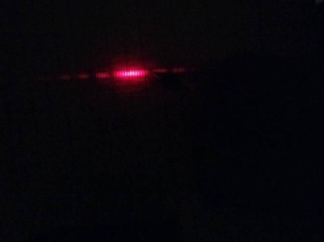
Figure 8. Interference pattern showing diffraction envelope and small fringes due to interference.

Good job Karlo. Continue being inspired in understanding physics. 🙂
– Ma’am Anj
LikeLike